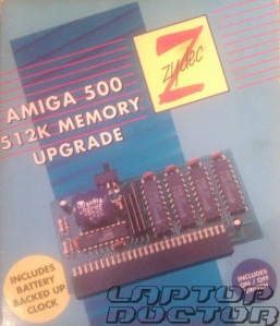
Although Amiga 500 was released with only 512kb of stock RAM it was very often bundled with memory expansion. For many users it was most important Amiga upgrade to buy and rightly so. as it not only made games look better (and in later years run at all) but allowed use of many productivity applications in a meaningful way.
A501 and it’s equivalent where so ubiquitous that Amiga 500 beefed up to 1Mb quickly became a standard, baseline that game programmers expected. There was variety of compatible memory upgrades that were following similar design principles. Like most of them Zydec’s Amram 500 included battery backed Real Time Clock.
Unfortunately, nickel batteries at the time weren’t designed to last 20 years and checking for battery damage should be your top priority whenever you buy or rescue Amiga. They have tendency to leak corrosive electrolyte which effects include damaged components, corroded PCB traces and even dead Amigas. They were used aplenty at the day and are very common circuit board wreckers. It’s easy enough to replace old battery with modern CR2032 at a budget.
As expected Workbench couldn’t read nor set date on the during the boor, so I removed the culprit from it’s trapdoor slot and started assessing the damage.
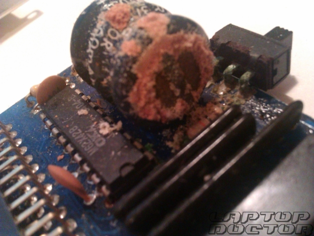
Sure enough, whole area around battery was covered in electrolyte. It’s small blessing that A500 relied on external Real Time Clock due to budget constrains as it keeps corrosives away from motherboard.
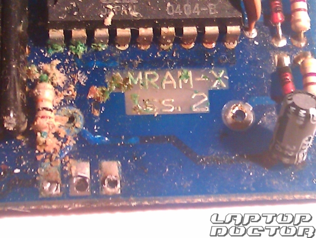
It isn’t pretty sight, especially green stuff on IC pins, but upgrades can be tinkered with or exchanged while Amiga stays functional, albeit with only 512k of system memory. Use q-tips dampened interchangeably in isopropyl alcohol and white vinegar to clean affected area.

It looks much better after cleaning. Electrolyte burned thru vias and traces, but really critical damage is concentrated in small area battery’s negative connector.
It was my first time recreating PCB traces and hope to do much better next time. At this point I decided it’s time to see how I’ve done, so Amram back into trapdoor went. Unfortunately as long as jumper was set to enable trapdoor memory, Amiga would greet me with sadness on her screen.

Memory is much more important to me than real time clock, so I decided to convert my expansion into 500+ compatible model by removing IC clock and supporting circuitry. At that point I already downloaded expansion schematics, but they had such poor resolution they were barely readable. I found all the info I needed on Big Book of Amiga Hardware. After comparing pictures of both models I desoldered all unnecessary parts and added some headers, just in case I’ll change my mind about having RTC.

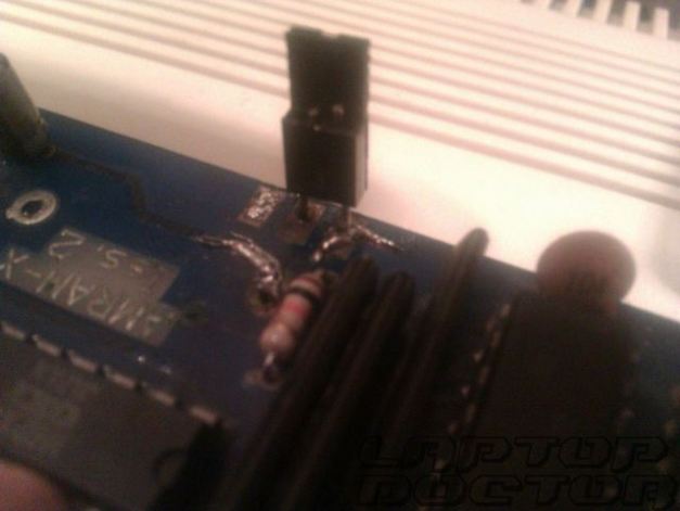
512k trapdoor expansion for Amiga in it’s most minimalistic form
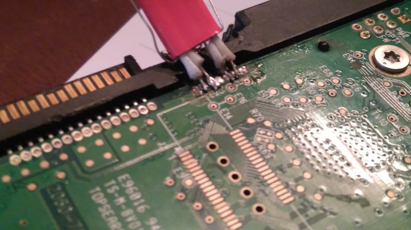
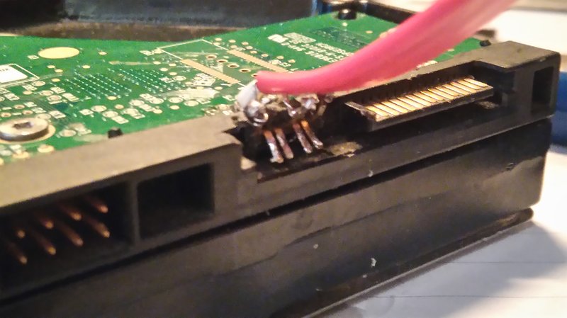
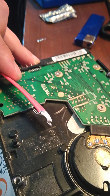
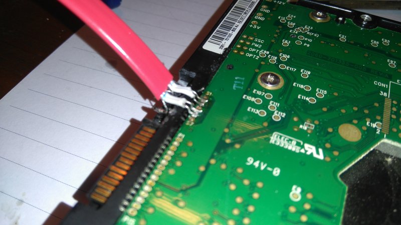
I decided not to rely on corroded traces and used jumper cables to bypass them. Instead of connecting PIN 16 of DRAM chip to jumper’s ON pin I connected it directly to PIN 32 on the connector and ran it to middle jumper to have it always ON and to spre. Thanks to corrosion there was no metal for solder to sink into in jumper thru holes, so cables are soldered to pins themselves.

With Amram 500 stripped to bare minimum I tried booting Workbench disk again. It loaded without Guru Meditation this time, but it didn’t recognized upgrade.
Troubleshooting
- Using multimeter I checked if expansion gets enough power from Amiga. Voltage between PIN 32 on trapdoor connector and ground (RF Shield or metal jacket on any of external ports) should be 5V.
- Individually checked if ram DIPs are being fed current. Thanks to pinouts on Amiga Stuff website I knew to measure voltage between PIN1 and PIN 10 of each memory chip. All four were being fed enough current.
- I checked continuity on all connections I resoldered earlier to find they are conducting as supposed.
- Then I realised I ran one cable on the other side of PCB than originally, connecting it through depopulated battery solder point. And surprise, surprise, no continuity there.
Let’s hope it worked! Amram 500(+) sits nice and tight in trapdoor, time to boot Workbench and see if my efforts paid back.
This slideshow requires JavaScript.
I don’t think there’s much more I can do without logic probe or oscilloscope, or is it? Would it help if I replaced decoupling caps and resistor banks? I guess if that wont work, it’s 1MB Chip Ram hack for me.